is time to lift the curtain.
Ingredients needed for this recipe.
As I always say, our essential hands, a touch of skill, some muscle strength and most importantly, who has the desire, the willingness or desire to do well.
Tools see photo A.
1-Millimeter Combination Wrenches 10, 12, 14mm, pictured a.
2-Allen wrench or screwdriver as punta12 mm.
Photo A. Several types of combination wrenches we are using.
Photo b. 12mm Allen head screwdriver, also serves an Allen wrench of the same size.
Parts needed, see picture B.
course are needed two databases that hold the headlamp with internal rubber are two on each side a lower and an upper , we must not overlook the two stretchable rubber covering each pole and finally the decorative rings are on top Stretch each rubber, see photo # B.
Steps to start the disassembly.
1-First located lower gum is located in the inner bottom in their respective cavity of each base.
Rubber inner bottom that goes into each base.
2-lower inner cavity where the rubber is described in the previous step, each base brings this design.
We 3-bottom placing the rubber inside the cavity prepared for it.
4-proper manner of rubber that must be accommodated.
5-outer upper gum which is mounted on each base.
6-This is the spot where the rubber must be mounted as described in the previous step, just the top of each base.
7-see, his mounts is easy, simply present him and make him a little pressure until completely fit.
8-With the tires mounted on each base, it is time to bring it to the natural habitat, which is none other than the space between the T's or upper and lower rods.
9-With care and will touch base by inserting the until it is aligned with the holes in the t's or rods.
10-The top must be perfectly aligned with the upper hole in the stem to above ...
11-the same with the bottom.
12-If successful, since the two bases should be given equally spaced and parallel to each other, be very careful not to scratch, especially as I If that had been freshly painted.
13-After the twelfth step, but seek one of two cordoned off for mounting tires.
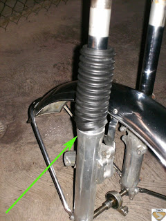
14-Each rubber as described in the previous step, should cover each cane, to facilitate my work, I had previously disarmed the whole picture.
15-As a guide, the thickest part of each wheel is going down.
16-A bit of oil to the edges can be helpful.
17-As retailers and if you look carefully, there is a notch at the top of each cane, it serves to hold each wheel.
18-Enter each wheel by the top of each stop staff, recalled that the thick part is going downhill.
19-apply more skill than strength to gradually introduce each wheel, be patient and do not use anything metal or edged for help here, because they can break the rubber, I use a plastic paddle and I was giving and giving until it was wearing.
Once they have placed each wheel and is properly secured at the bottom, proceed to assemble the decorative rings are on top of each tire.
21-Each ring is inserted into its respective stick and dropped further to final installation, the flat face down .
22-get as close as we can complete all rods / front fender and align as much as we can with the bottom holes on each base.
23-At this point can pass the pipe to the caliper, gradually presented in its final location.
24-Well, now with some force, we went around the joint between the lower holes in each base.
25-When every stick poke out the top of the stem to top, the signal that this is the right level of stop.
26-Another shot indicating that the rods are at their proper installation.
27-A, then we must push hard each stick, for it will locate two 14mm bolts that are located in the bottom of each base.
28-Using a 14mm wrench tightened to satiety, we do not want a staff that we release in full drive, do yes?.
29-We will do the same in the top of each T or steering head, tighten firmly.
12mm 30-Two keys will help us execute this task well.
31-In this photo, once you have passed the pipe due to caliper site, because we fix it at its base, for this, we align and position the 10mm bolt from the base and the hole.
32-Then, we present the caliper to the caliper to the base B in between, it is easier to move the caliper to the base tighter pipeline in reverse assure you.
Once the two have been fully aligned we press caliper hand the two Allen bolts to where you can ....
34-for then tightening them completely with a 12mm Allen wrench or socket.
As I always say, has been a pleasure to share with you this part of my Geisha armed, soon continue with the completion of this part.


0 comments:
Post a Comment